Steel Grade — What Material Thread Gauges Are Made From
Thread gauges must be made from a steel that combines high hardness, good dimensional stability after heat treatment, and excellent wear resistance. Not all steel grades provide these properties — and the steel grade is the foundation of gauge quality that everything else is built on.
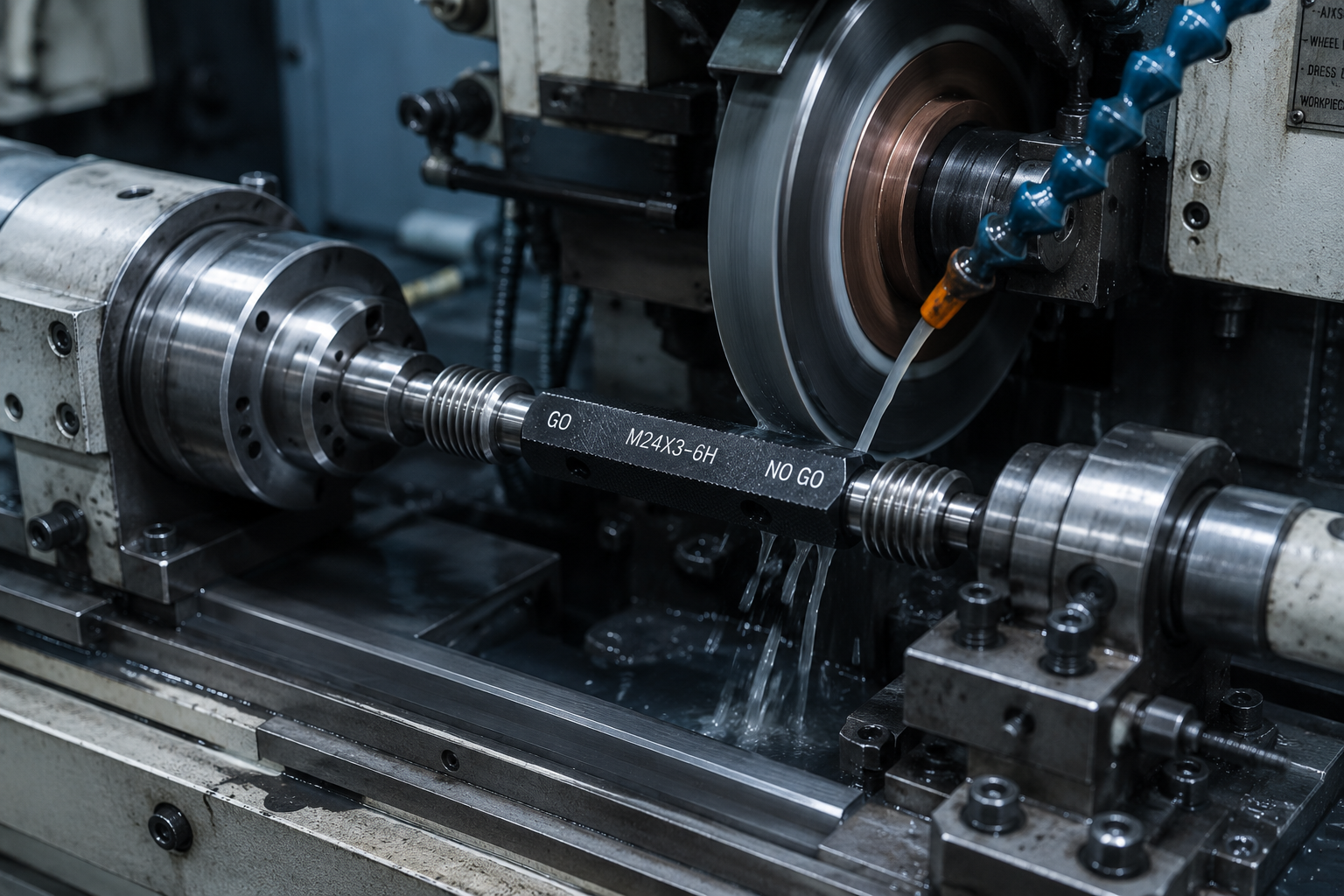
Why Steel Grade Matters
A gauge made from an inferior steel — insufficient carbon content, wrong alloying elements, or inadequate purity — cannot achieve the required hardness after heat treatment. A gauge at HRC 52 instead of HRC 60 wears at roughly twice the rate under the same inspection conditions, meaning the pitch diameter drifts out of its tolerance limit in half the expected time. The difference is invisible on delivery but becomes apparent within the first months of production use.
Hardness — Why HRC 58–64 Is the Correct Range
Thread gauge hardness is measured on the Rockwell C scale (HRC). The required range for precision thread gauges is HRC 58–64. This range is not arbitrary — it represents the balance between maximum wear resistance (requiring high hardness) and adequate toughness to resist chipping and cracking during grinding and use.
What Each HRC Level Means
Why Too Hard Is Also a Problem
Above HRC 64, tool steel becomes increasingly brittle. A gauge at HRC 65+ is prone to micro-chipping on thread flanks during grinding and during production use — particularly at thread roots and crests where stress concentrations are highest. Chipping creates burrs on the gauge thread that cause false rejections and damage workpiece threads.
The HRC 58–64 range achieves maximum practical wear resistance while maintaining sufficient toughness to survive the mechanical stresses of production inspection use.
How to verify: Ask the supplier for the hardness value recorded in the calibration certificate or material test report. A qualified manufacturer measures and records hardness as part of the production process. A hardness value is not an estimate — it is a measured fact.
Surface Finish — Ra ≤ 0.2μm on Thread Flanks
Surface roughness (Ra) is the average arithmetic deviation of the surface profile from the mean line, measured in micrometres. For thread gauge flanks and bearing surfaces, Ra ≤ 0.2μm is the required specification. This is a very smooth surface — approximately 8 micro-inches in imperial units.
| Surface (Ra μm) | Description | Thread Gauge Application |
|---|---|---|
| Ra 0.1 | Mirror finish — optical quality | Reference and master gauges |
| Ra 0.2 ✓ | Very fine ground and lapped surface | Production thread gauges — required specification |
| Ra 0.4 | Fine ground surface | Borderline — acceptable for low-volume use only |
| Ra 0.8+ | Standard ground surface | Not acceptable for thread gauges — excessive wear |
Why Surface Roughness Affects Gauge Accuracy
A rough gauge surface — even one that appears smooth to the naked eye — causes two problems in production use. First, the surface peaks (asperities) of the gauge thread contact the workpiece thread at high local pressure, accelerating wear of both the gauge and the workpiece thread. Second, the rough surface traps chips and contaminants between gauge and workpiece, producing inconsistent results and increasing the apparent friction during inspection.
A gauge with Ra 0.8μm on thread flanks will wear to its calibration limit in approximately one-quarter the time of a gauge with Ra 0.2μm — all other factors being equal. The lapping process after CNC grinding is what brings the surface to Ra ≤ 0.2μm, and it is this step that low-cost manufacturers most commonly skip to reduce production time and cost.
CNC Grinding Tolerance — ±0.001mm on Pitch Diameter
The pitch diameter is the most critical dimension of a thread gauge. It directly controls the GO/NO-GO acceptance decision — whether parts are accepted or rejected. Thread gauge standards (ISO 1502, ASME B1.2) specify the allowable limits for the gauge pitch diameter, and the gauge must be ground to within those limits.
For the M12×1.75 6H example, the total tolerance band for the GO gauge pitch diameter is 0.010mm. A gauge ground to ±0.001mm accuracy will have its pitch diameter within 0.001mm of the target — leaving 80% of the tolerance band as a buffer against wear before the gauge exceeds its limit.
A gauge ground to only ±0.005mm accuracy may start very close to the tolerance limit — and reach the limit after minimal wear. This is why the calibration certificate must show the actual measured value, not just a conformance statement. A value close to the limit tells you the gauge has less wear budget remaining.
Check the certificate: Compare the actual measured pitch diameter with the upper and lower limits. A well-manufactured gauge should have its actual value close to the centre of the tolerance band — not close to either limit. See our Calibration Certificate Reading Guide.
Heat Treatment and Dimensional Stability
Hardening tool steel is a multi-stage process. Skipping or shortening any stage produces a gauge that may achieve the target hardness initially but loses dimensional stability over time — causing the gauge dimensions to drift even without mechanical wear.
| Treatment Stage | Purpose | If Skipped |
|---|---|---|
| Hardening | Rapid quench from austenitising temperature to achieve martensitic structure and target HRC | Insufficient hardness — gauge wears rapidly |
| Sub-zero treatment (-80°C to -120°C) | Converts retained austenite to martensite — eliminates a metastable phase that causes dimensional change over time | Gauge dimensions drift after grinding — calibration certificate values become inaccurate within months |
| Stress relief tempering | Reduces residual stresses from quenching and grinding — prevents micro-cracking and dimensional drift | Gauge develops micro-cracks under production stress — unpredictable dimensional change |
| Ageing / seasoning | Further stabilises dimensions at room temperature over time before final grinding | Gauge dimensions change slightly after delivery — calibration certificate may not match actual dimensions after a few weeks of storage |
Sub-zero treatment is the step most commonly skipped by low-cost manufacturers. A gauge without sub-zero treatment may appear dimensionally correct on delivery and pass initial calibration, but retained austenite in the steel gradually transforms to martensite over weeks and months — causing the gauge pitch diameter to change by 2–5 micrometres. This change is enough to push a gauge that started close to the tolerance limit out of specification without any visible wear.
How to Identify a High-Quality Thread Gauge — 6 Indicators
- Calibration certificate shows actual measured values — not just “conforms to specification.” The actual pitch diameter, major diameter, minor diameter, pitch, and thread angle must be stated, along with the upper and lower limits. See How to Read a Calibration Certificate for what to check.
- Hardness value is recorded — either in the calibration certificate or a separate material test report. The value must be in the HRC 58–64 range. A supplier who cannot provide this value has not measured it.
- Surface finish specification is stated — Ra ≤ 0.2μm on thread flanks. This should appear in the product specification or the quality documentation accompanying the gauge.
- Certificate issued by ISO/IEC 17025 accredited lab — with a verifiable accreditation number. The accreditation body (CNAS, UKAS, A2LA, DAkkS) can be checked online. See Manufacturer vs Trader for why this matters.
- Thread flanks have a lapped finish — visible as a very uniform, slightly matte surface. A ground-only surface has a directional grinding pattern; a lapped surface has a more diffuse, non-directional finish. If you can see clear grinding marks on the thread flanks, the gauge has not been lapped.
- Handle engravings are sharp and complete — thread designation, tolerance class, GO/NO-GO marking, and serial number must all be clearly legible. Faint or incomplete engravings suggest poor quality control in the production process.
Signs of Low-Quality Thread Gauges
- Certificate shows no actual measured values — only “pass” or “conforms”
- No hardness value or surface finish specification documented
- Certificate issuer has no verifiable ISO/IEC 17025 accreditation
- Visible grinding marks on thread flanks — not lapped
- Handle engravings are faint, incomplete, or poorly positioned
- Thread feels rough or catches when rotated by hand
- GO gauge wears to calibration limit within 3–6 months of standard use
- Pitch diameter drifts without obvious wear marks — sub-zero not done
- Thread flanks show polishing marks within weeks of use
- Gauge produces inconsistent results on the same part
- Gauge fails calibration significantly before the scheduled interval
- Rust appears on thread surface within months of delivery
Frequently Asked Questions
Thread Gauges Built to Last — Material and Hardness Certified
Every GageTools gauge is manufactured from high-carbon alloy tool steel, hardened to HRC 58–64 with full sub-zero treatment, ground to ±0.001mm, and lapped to Ra ≤ 0.2μm. The calibration certificate shows actual measured values for every critical dimension. MOQ 1 piece. Standard sizes in 72 hours.
✓ 20+ years gauge manufacturing
✓ ISO 9001:2015 certified
✓ In-house CNC grinding & inspection
✓ Drawing / RFQ reply within 24h
Click the email address to copy · Response within 24 hours · ISO/IEC 17025 certificate on request
Pingback: Thread Gauge Storage and Handling: How to Protect Your Gauges and Extend Their Life - GageTools
Pingback: Custom Thread Gauge Sampling: Process, Cost and Timeline Before You Order in Bulk - GageTools