Thread Reference Data
Thread Size Charts & Gauge Selection Tables
Reference tables for Metric threads, UNC and UNF threads, BSP threads, NPT threads and general-purpose ACME threads. Use the data to prepare an RFQ, then verify the current standard, complete thread designation and inspection method.
Find the Right Thread Gauge →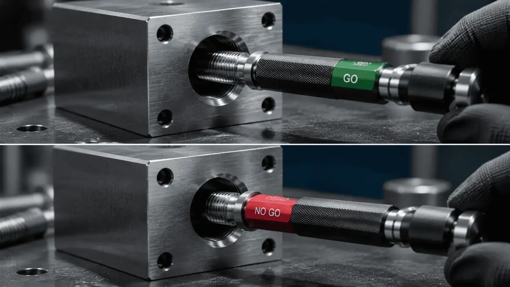
What is this thread chart used for? It lists common nominal sizes for Metric, UNC/UNF, BSP/NPT and ACME threads so you can identify the correct thread callout before ordering an inspection gauge. It is a reference for RFQ preparation only — the tolerance class and standard on your drawing still govern the final gauge design.
Find the thread standard and class in the tables below, then request a matching GO/NO-GO thread plug gauge or thread ring gauge — or send a drawing for a non-standard thread.
Find the Right Thread Gauge → View GO/NO-GO Thread Gauges →How To Use This Page
Confirm the Thread Before Ordering a Gauge
The tables contain common nominal data and do not define final workpiece or gauge acceptance limits.
Confirm the Standard
Identify Metric ISO, UN, G/R/Rp/Rc, NPT, NPTF, ACME or a drawing-specific thread.
Confirm the Gauge
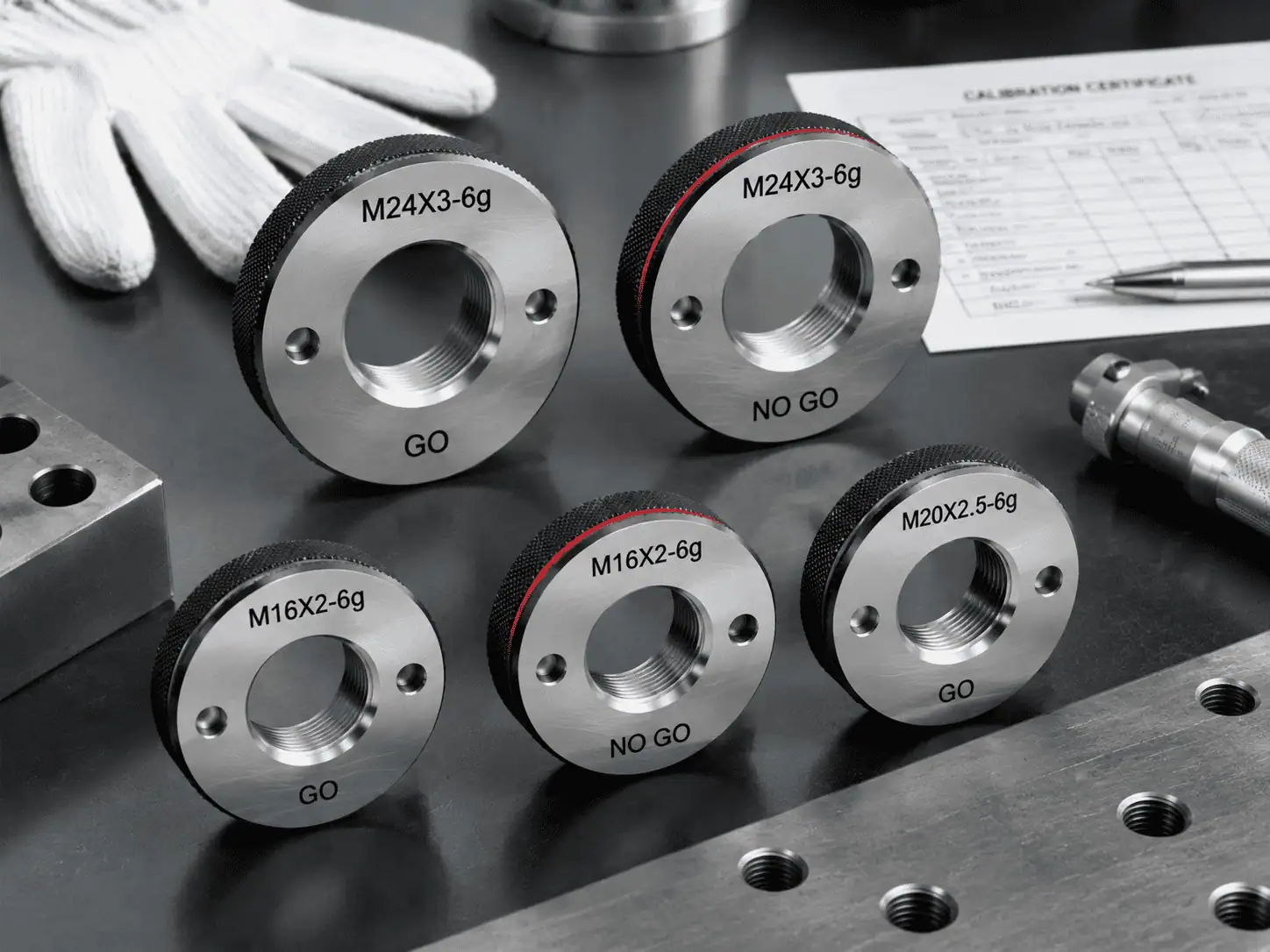
Internal product threads normally use plug gauges. External threads normally use ring gauges.
Send Complete RFQ Data
Include class, hand, starts, lead, coating condition, quantity, certificates and drawing.
ISO 261 / ISO 724 / ISO 965 / ISO 1502
Metric Thread Chart
Metric thread callouts use nominal diameter and pitch, such as M12 x 1.75. The class on the drawing determines the inspection limits.
- Thread angle: 60 degrees
- Common internal workpiece class: 6H
- Common external workpiece class: 6g
- Gauging system: ISO 1502
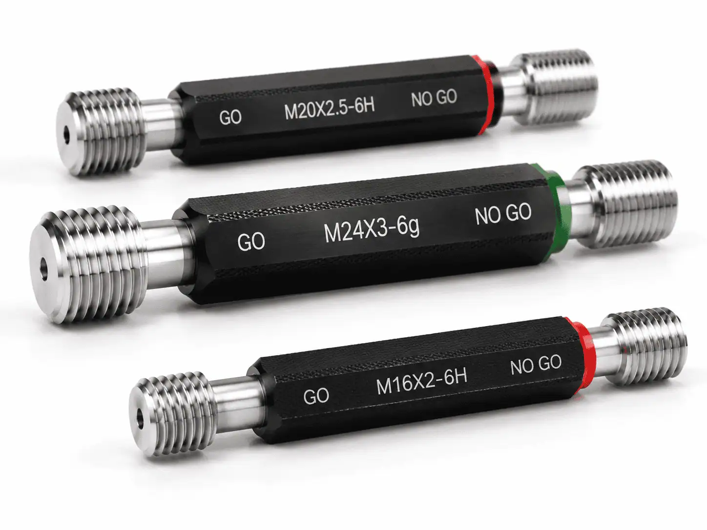
Metric Coarse Reference
Common Metric Sizes
Nominal values and approximate cutting-tap drill sizes for RFQ preparation.
| Thread | Pitch mm | Nominal Major Diameter mm | Approx. Cut-Tap Drill | Gauge Selection | RFQ |
|---|---|---|---|---|---|
| M2 x 0.4 | 0.40 | 2.00 | 1.6 mm | Plug for 6H internal | Quote |
| M3 x 0.5 | 0.50 | 3.00 | 2.5 mm | Plug for 6H internal | Quote |
| M4 x 0.7 | 0.70 | 4.00 | 3.3 mm | Plug for 6H internal | Quote |
| M5 x 0.8 | 0.80 | 5.00 | 4.2 mm | Plug for 6H internal | Quote |
| M6 x 1.0 | 1.00 | 6.00 | 5.0 mm | Plug for 6H internal | Quote |
| M8 x 1.25 | 1.25 | 8.00 | 6.8 mm | Plug for 6H internal | Quote |
| M10 x 1.5 | 1.50 | 10.00 | 8.5 mm | Plug for 6H internal | Quote |
| M12 x 1.75 | 1.75 | 12.00 | 10.2 mm | Plug for 6H internal | Quote |
| M16 x 2.0 | 2.00 | 16.00 | 14.0 mm | Plug for 6H internal | Quote |
| M20 x 2.5 | 2.50 | 20.00 | 17.5 mm | Plug for 6H internal | Quote |
| M24 x 3.0 | 3.00 | 24.00 | 21.0 mm | Plug for 6H internal | Quote |
| M30 x 3.5 | 3.50 | 30.00 | 26.5 mm | Plug for 6H internal | Quote |
ASME B1.1 / ASME B1.2
UNC and UNF Thread Chart
2B and 2A identify common internal and external workpiece classes, not universal gauge classes.
| Thread | Series | TPI | Nominal Major Diameter in | Typical Workpiece / Gauge | RFQ |
|---|---|---|---|---|---|
| #4-40 | UNC | 40 | 0.1120 | Plug: 2B internal / ring: 2A external | Quote |
| #6-32 | UNC | 32 | 0.1380 | Plug: 2B internal / ring: 2A external | Quote |
| #8-32 | UNC | 32 | 0.1640 | Plug: 2B internal / ring: 2A external | Quote |
| #10-24 | UNC | 24 | 0.1900 | Plug: 2B internal / ring: 2A external | Quote |
| 1/4-20 | UNC | 20 | 0.2500 | Plug: 2B internal / ring: 2A external | Quote |
| 5/16-18 | UNC | 18 | 0.3125 | Plug: 2B internal / ring: 2A external | Quote |
| 3/8-16 | UNC | 16 | 0.3750 | Plug: 2B internal / ring: 2A external | Quote |
| 1/2-13 | UNC | 13 | 0.5000 | Plug: 2B internal / ring: 2A external | Quote |
| 1/4-28 | UNF | 28 | 0.2500 | Plug: 2B internal / ring: 2A external | Quote |
| 3/8-24 | UNF | 24 | 0.3750 | Plug: 2B internal / ring: 2A external | Quote |
| 1/2-20 | UNF | 20 | 0.5000 | Plug: 2B internal / ring: 2A external | Quote |
| 3/4-16 | UNF | 16 | 0.7500 | Plug: 2B internal / ring: 2A external | Quote |
ISO 228 / ISO 7 / ASME B1.20
BSP and NPT Thread Reference
Confirm the complete designation, internal or external form and applicable gauging system.
- G or BSPP: parallel 55-degree thread under ISO 228-1
- R external taper, Rp internal parallel and Rc internal taper
- NPT: 60-degree taper thread under ASME B1.20.1
- NPTF: dryseal thread with separate inspection requirements
| Nominal Size | BSP TPI | NPT TPI | Required Designation | Order Note | RFQ |
|---|---|---|---|---|---|
| 1/8 | 28 | 27 | G / R / Rp / Rc / NPT / NPTF | Confirm system and internal/external | Quote |
| 1/4 | 19 | 18 | G / R / Rp / Rc / NPT / NPTF | Confirm system and internal/external | Quote |
| 3/8 | 19 | 18 | G / R / Rp / Rc / NPT / NPTF | Confirm parallel or taper | Quote |
| 1/2 | 14 | 14 | G / R / Rp / Rc / NPT / NPTF | Same TPI does not mean interchangeable | Quote |
| 3/4 | 14 | 14 | G / R / Rp / Rc / NPT / NPTF | BSP is 55 degrees; NPT is 60 degrees | Quote |
| 1 | 11 | 11.5 | G / R / Rp / Rc / NPT / NPTF | NPT: L1 plug internal / L1 ring external | Quote |
| 1-1/2 | 11 | 11.5 | G / R / Rp / Rc / NPT / NPTF | NPTF may require supplemental checks | Quote |
| 2 | 11 | 11.5 | G / R / Rp / Rc / NPT / NPTF | Never select from nominal size alone | Quote |
ASME B1.5
General-Purpose ACME Thread Chart
Confirm class, hand, number of starts, lead and whether the product thread is internal or external.
| Thread | TPI | Pitch in | Angle | Class / Inspection | RFQ |
|---|---|---|---|---|---|
| 1/4-16 ACME | 16 | 0.0625 | 29 deg | Specify 2G/3G/4G; plug internal / ring external | Quote |
| 3/8-12 ACME | 12 | 0.0833 | 29 deg | Specify 2G/3G/4G; plug internal / ring external | Quote |
| 1/2-10 ACME | 10 | 0.1000 | 29 deg | Specify 2G/3G/4G; plug internal / ring external | Quote |
| 3/4-6 ACME | 6 | 0.1667 | 29 deg | Specify 2G/3G/4G; plug internal / ring external | Quote |
| 1-5 ACME | 5 | 0.2000 | 29 deg | Specify 2G/3G/4G; plug internal / ring external | Quote |
| 1-1/2-4 ACME | 4 | 0.2500 | 29 deg | Specify 2G/3G/4G; plug internal / ring external | Quote |
Cutting Tap Reference
Tap Drill Formula and Sizes
For common metric cutting taps, nominal diameter minus pitch is an approximate starting value. Form and roll taps require manufacturer-specific drill sizes.
Approximate cut-tap drill = Nominal diameter - Pitch
Example: M10 x 1.5 = 10 - 1.5 = 8.5 mm

| Tap Size | Pitch mm | Approx. Drill mm | Common Drill | Inspection Gauge | RFQ |
|---|---|---|---|---|---|
| M3 x 0.5 | 0.50 | 2.50 | 2.5 mm | M3 x 0.5 6H plug | Quote |
| M4 x 0.7 | 0.70 | 3.30 | 3.3 mm | M4 x 0.7 6H plug | Quote |
| M5 x 0.8 | 0.80 | 4.20 | 4.2 mm | M5 x 0.8 6H plug | Quote |
| M6 x 1.0 | 1.00 | 5.00 | 5.0 mm | M6 x 1.0 6H plug | Quote |
| M8 x 1.25 | 1.25 | 6.75 | 6.8 mm | M8 x 1.25 6H plug | Quote |
| M10 x 1.5 | 1.50 | 8.50 | 8.5 mm | M10 x 1.5 6H plug | Quote |
| M12 x 1.75 | 1.75 | 10.25 | 10.2 mm | M12 x 1.75 6H plug | Quote |
| M16 x 2.0 | 2.00 | 14.00 | 14.0 mm | M16 x 2.0 6H plug | Quote |
Download and Attribution
Download, Cite or Embed This Chart
Use the PDF internally or copy the attribution when referencing this page.
Thread Size Charts and Gauge Selection Reference
Metric, UNC/UNF, BSP/NPT, ACME, cutting-tap drill data, RFQ checklist and citation instructions.
Download the Free PDFCopy the Reference
Link to the live page so readers can find the newest revision.
Technical disclaimer and referenced standards
Technical reference only. This chart contains common nominal sizes and approximate cutting-tap drill starting values. It does not define acceptance limits and is not a substitute for the current governing standard, approved drawing or calibrated inspection procedure.
Referenced systems include ISO 261, ISO 724, ISO 965, ISO 1502, ASME B1.1, ASME B1.2, ISO 228, ISO 7, ASME B1.20.1, ASME B1.20.3, ASME B1.20.5 and ASME B1.5.
How to Use a Thread Chart to Pick the Right Gauge
A thread chart is most useful when you read it in a fixed order. Before ordering a gauge, work through these steps with the drawing and the chart side by side.
- Identify the thread system. Metric (M), Unified (UNC, UNF, UNEF), pipe (NPT, BSP G or R) or trapezoidal/Acme. The prefix or suffix on the drawing usually tells you.
- Read the nominal size and pitch. For metric threads the pitch is in mm (M10×1.25); for inch threads it is threads per inch (3/8-24). If a metric size has no pitch, it is coarse pitch.
- Find the tolerance class. 6H or 6g for metric, 2B or 2A for Unified. The class decides which GO/NO-GO gauge you need.
- Decide internal or external. Internal threads are checked with plug gauges; external threads with ring gauges.
- Check special requirements. Left-hand thread, blind-hole depth, coating, or a customer-specified gauging standard.
Reading across the wrong row is a common slip on large charts, especially between coarse and fine pitch rows of the same diameter. Confirm the pitch twice before ordering.
With these five items, the gauge specification is complete. Missing any of them is the main reason for wrong gauges and repeat orders.
Tap Drill Size vs Gauge Size
Thread charts often list tap drill sizes next to thread sizes, and the two are sometimes confused. The tap drill sets the hole’s minor diameter before tapping; it is not a gauge dimension. The thread plug gauge checks the finished pitch diameter and form after tapping.
| Thread | Common tap drill | Gauge to order |
|---|---|---|
| M6×1 | 5.0 mm | M6×1-6H GO/NO-GO plug |
| M10×1.5 | 8.5 mm | M10×1.5-6H GO/NO-GO plug |
| M18×1.5 | 16.5 mm | M18×1.5-6H GO/NO-GO plug |
| 1/4-20 UNC | No. 7 (5.1 mm) | 1/4-20 UNC-2B GO/NO-GO plug |
| 3/8-16 UNC | 5/16 in (7.94 mm) | 3/8-16 UNC-2B GO/NO-GO plug |
A correct drill size does not guarantee a good thread. Tap wear, runout and chip packing can still put the pitch diameter out of tolerance, which only a gauge will detect. A plain plug gauge is sometimes used to check the minor diameter separately.
Common Look-Alike Threads
Some thread sizes from different systems are close enough to start by hand, then bind or leak. These pairs cause the most mix-ups in incoming inspection.
| Pair | Why they are confused | How to tell them apart |
|---|---|---|
| M10×1.5 vs 3/8-16 UNC | Both about 10 mm diameter, pitch 1.5 mm vs about 1.59 mm, both 60° | Pitch gauge in mm and TPI; 3/8 in is 9.525 mm |
| 1/2 BSP vs 1/2 NPT | Both 14 TPI and similar diameter | BSP is 55° Whitworth form; NPT is 60° and always tapered |
| M18×1.5 vs 3/4-16 UNF | Close diameters, pitch 1.5 mm vs about 1.59 mm | 3/4 in is 19.05 mm vs 18 mm; check pitch over several threads |
Hand tools separate these pairs, but the final check should always be the correct GO/NO-GO gauge. For pipe threads, see our NPT vs BSP gauge comparison; for Unified series, see UNC vs UNF vs UNEF explained.
Where to Find Tolerance Limits
A thread chart gives nominal sizes and pitches, but a gauge is made to tolerance limits: minimum and maximum pitch diameter, major and minor diameter for the specified class. These come from ISO 965 for metric threads, ASME B1.1 for Unified threads, and the pipe standards for NPT and BSP. Gauge dimensions themselves are defined in ISO 1502 (metric) and ASME B1.2 (Unified).
For metric sizes, our metric thread plug gauge size chart with tolerance limits lists pitch diameter limits by size. If your thread is non-standard, send the drawing and we will quote a custom gauge.
Thread Chart Questions
Is the tap drill size the same as the gauge size?
No. The tap drill size sets the hole diameter before tapping and roughly controls the thread’s minor diameter. A thread plug gauge checks the finished thread’s pitch diameter and form. You need the thread size, pitch and tolerance class to order a gauge; the tap drill size is not used in the gauge specification.
What does it mean if a metric thread size has no pitch?
A metric size written without a pitch, such as M10, means the ISO coarse pitch, which is 1.5 mm for M10. Fine pitches are always written in full, for example M10×1.25. When ordering gauges, write the pitch explicitly to avoid mistakes, even for coarse threads.
Can I use a thread chart to check if a part is in tolerance?
Not directly. A chart gives nominal dimensions and pitches, which help identify the thread. Tolerance acceptance needs pitch diameter limits for the class and a gauge or measurement system. For production inspection, use GO/NO-GO thread gauges made to ISO 1502 or ASME B1.2.
Why does a nut start on a bolt but then bind?
The most common cause is a look-alike thread from a different system, such as an M10×1.5 nut on a 3/8-16 UNC bolt. The diameters are close and the pitch difference is small, so the first turns engage before the threads drift out of phase. Other causes are damaged threads, burrs or oversize coatings.
Need a Gauge for This Thread?
Request a Thread Gauge Quote
Send the complete callout, standard, internal or external form, class, hand, starts, lead, coating condition, quantity and certificate requirement.
Choose the Gauge Direction
Need the Right Gauge?
Send Your Drawing or Inspection Requirement
Share the gauge type, part drawing, thread standard, tolerance, quantity and delivery country. Our team will recommend a suitable standard or custom inspection gage.
Send Drawing for Review → WhatsApp Technical Team →