
Need gauges for this? GageTools manufactures GO/NO-GO thread plug gauges and thread ring gauges in Dongguan, China. Standard sizes ship from stock within 72 hours, MOQ is 1 piece, and every RFQ gets a reply within 24 hours — request a quote.
Why the Gauge Drawing Deserves a Proper Review
When you order a custom thread gauge from a drawing, the gauge maker usually converts your part requirement into a gauge drawing or a gauge specification sheet. That document is what the grinding and lapping shop works to. If it contains a wrong class, a wrong pitch or a missing requirement, the finished gauge will faithfully reproduce the mistake.
The review is not about checking the gauge maker’s arithmetic line by line. It is about confirming that the gauge described is the gauge your inspection needs: the right thread, the right limits, the right length and the right condition. Most expensive gauge errors are not calculation errors. They are misunderstandings about what the part is, where it is checked and what state it is in when it is gauged.
A gauge made to the wrong specification cannot be corrected by adjustment in most cases. A solid plug or ring ground to the wrong pitch diameter is scrap, and the replacement starts the lead time again. That is why a short review before production is one of the cheapest quality steps in the whole purchase.
The Drawing Review Checklist
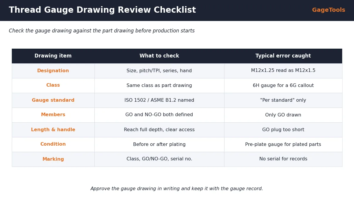
Work through the gauge drawing in the same order every time. The table below lists the items that cause most problems, with the kind of error each check is designed to catch.
| Drawing item | What to check | Typical error caught |
|---|---|---|
| Thread designation | Size, pitch or TPI, series, hand and number of starts match the part drawing | M12x1.25 read as M12x1.5; UNF read as UNC |
| Tolerance class | Class on the gauge equals the class on the part | 6H gauge drawn for a 6G callout; 2B for 3B |
| Gauge standard | ISO 1502, ASME B1.2 or the customer specification is named | No standard stated, so limits are unclear |
| Gauge members | GO and NO-GO both defined, or clearly one member only | Only GO drawn when a full set was needed |
| Gauging length | Thread length on the plug or ring suits the part | GO plug shorter than the full thread depth |
| Handle and body | Handle style, overall length and reach suit access | Handle too large for a recessed port |
| Condition | Before or after plating or coating | Pre-plate gauge ordered for plated parts |
| Marking | Designation, class, GO/NO-GO, serial number | No serial number for calibration records |
| Documents | Certificate type and any extra reports | ISO/IEC 17025 certificate needed but not requested |
If any line cannot be confirmed from the drawing, ask the question before you approve. A reply that takes one day is better than a gauge that takes two weeks to remake.
Checking the Thread Designation and Class
Start by laying the part drawing and the gauge drawing side by side. Read the thread callout character by character. Fine-pitch metric threads are a common trap: M16x1.5 and M16x2 look similar at a glance but need completely different gauges. On unified threads, confirm the series (UNC, UNF, UNEF or UNS) and the class (2B/3B for internal, 2A/3A for external).
Tolerance class deserves a second look. For internal metric threads with an H tolerance position, the fundamental deviation is zero, so the GO plug is the same for 4H, 5H, 6H and 7H; only the NO-GO plug changes with the grade. For the G position the GO plug itself is different. If the gauge drawing shows a 6G GO plug but your part is 6H, every part will be judged against the wrong limit. Our 6G vs 6H comparison explains the difference.
Left-hand threads and multi-start threads must be stated explicitly on the gauge drawing and on the gauge itself. A left-hand gauge that is not clearly marked will eventually be picked up by someone expecting a right-hand thread. See our notes on left-hand thread gauges.
Gauge Standard and Gauge Limits
The gauge drawing should name the standard the gauge is made to. For ISO metric threads this is normally ISO 1502; for unified inch threads it is ASME B1.2. These standards define the gauge tolerances, the wear allowance on the GO member and the form of the NO-GO member. If your customer has its own gauge specification, it overrides the general standard and should be referenced by number and revision.
- GO member: full thread form, checks the functional size at the maximum-material limit.
- NO-GO member: truncated form and shorter length, checks pitch diameter at the least-material limit, following Taylor’s principle.
- Ring gauges: confirm whether setting plugs are part of the order and which standard they follow.
- Non-standard limits: if your part uses modified pitch diameter limits, the values must be written on the drawing, not implied.
You do not need to recalculate every gauge dimension, but you should confirm that the limits are derived from the right thread and class. If the gauge maker lists pitch diameter values, compare them with your own thread tables as a sanity check.
“Per standard” is not a specification when the standard is not named. A gauge drawing that says only “GO/NO-GO per standard” leaves the gauge maker to choose. Always write the standard, the class and, for special threads, the numeric limits.
Gauge Geometry: Length, Handle and Access
A gauge can have perfect thread limits and still be unusable on the part. Geometry problems usually show up only when the first gauge reaches the shop floor, so check them on paper first.
| Geometry item | Question to ask | If it is wrong |
|---|---|---|
| GO plug thread length | Does it reach the full required thread depth? | Short or incomplete threads at the bottom are never checked |
| Blind hole clearance | Is the gauge end suitable for the hole bottom and runout? | Gauge bottoms out and gives a false reject |
| Handle diameter | Will the handle clear bosses, walls and adjacent features? | Gauge cannot be used on the finished part |
| Overall reach | Is the port or thread deep inside a housing? | Extension handle needed after delivery |
| Ring outside diameter | Will the ring clear shoulders and flanges? | Ring cannot run onto a shouldered stud |
| Weight | Can the operator control the gauge by hand? | Heavy gauges get dropped or forced |
For blind holes, state the minimum full thread depth that must be gauged and the drill depth. Our guide to thread gauges for blind holes explains how to specify depth and clearance so the GO plug checks the whole thread.
Plating, Coating and Special Conditions
The condition in which the part is gauged changes the limits the gauge must represent. If threads are gauged after zinc plating, anodising or another coating, the gauge limits must suit the finished part. If they are gauged before plating, the process needs a coating allowance and a different gauge. The drawing review should confirm which of these the gauge is designed for.
Write the condition on the gauge drawing in plain words, such as “gauge for threads before plating” or “gauge for finished threads after coating”. Our article on thread gauges before or after plating covers how to decide.
- Taper threads (NPT, BSPT, R/Rc): the drawing shows L1 plug or ring gauges and the stand-off reference, not GO/NO-GO turns.
- Multi-start threads: number of starts, lead and pitch must all be stated.
- Acme and trapezoidal threads: confirm the class and whether the fit is general purpose or centralising.
- Special pitch diameter limits: numeric values on the drawing, with a note that the gauge is non-standard.
Marking, Identification and Documentation
Marking is part of the gauge specification, not an afterthought. Check that the drawing shows what will be engraved or laser-marked on each member: thread designation, class, GO or NO-GO (or NOT GO), hand if left-hand, and a unique serial number. If your plant uses its own gauge ID format, put it on the drawing so it is applied at manufacture.
| Marking or document | Why it matters | Where to specify |
|---|---|---|
| Thread designation and class | Operator picks the right gauge | Gauge drawing marking note |
| GO / NO-GO identification | Members cannot be confused | Marking note, colour code if used |
| Serial number | Links gauge to calibration record | Marking note or order line |
| Customer ID format | Fits your gauge register | Purchase order and drawing |
| Calibration certificate | Proves measured size | Order line, e.g. ISO/IEC 17025 on request |
If you need an ISO/IEC 17025 calibration certificate, state it on the order. The certificate records the measured size of each member, so it becomes the first entry in the gauge’s calibration history.
A Simple Drawing Review Workflow
Drawing reviews work best when the same people follow the same steps. In a small company this may be one quality engineer; in a larger one, quality and production sign together.
- Receive the gauge drawing and log it against the purchase order and part number.
- Compare the designation with the current revision of the part drawing.
- Confirm the standard, class and members (GO, NO-GO, setting plugs).
- Check geometry against the part model or a sample part.
- Confirm condition, marking and documents.
- Approve in writing or return comments; keep the approved revision on file.
Keep the approved drawing with the gauge record. When the gauge is replaced years later, the approved drawing makes the repeat order quick and removes guesswork.
Common Drawing Review Mistakes
| Mistake | Consequence | Prevention |
|---|---|---|
| Reviewing against an old part revision | Gauge matches an obsolete thread | Always check the current revision |
| Approving without reading the class | Wrong limits for every part | Read class on both drawings aloud |
| Ignoring the gauging length | Bottom threads never inspected | Compare with full thread depth |
| Assuming plating condition | Good parts rejected or bad accepted | State the condition in words |
| No written approval | Disputes over what was agreed | Sign and date the approved drawing |
After approval, the next quality step is inspection of the delivered gauge. Our sample approval checklist covers what to check when the first gauge arrives.
What to Send When Ordering Custom Thread Gauges
The better the information at the RFQ stage, the fewer questions appear on the gauge drawing. Send the following with your request:
- Part drawing, current revision, with the full thread callout
- Gauge types needed: plug, ring, GO, NO-GO, setting plugs
- Gauge standard or customer gauge specification
- Thread depth, access limits and any handle requirement
- Plating or coating condition at the time of gauging
- Marking requirements and your gauge ID format
- Quantity and certificate requirement (ISO/IEC 17025 available on request)
Send the drawing and we will confirm the gauge design before quoting. You can also read how to order custom thread gauges for the full ordering process.
Need a Custom Thread Gauge Made to Your Drawing?
Send your part drawing, thread callout, gauging condition and quantity. We confirm the gauge design with you before production and reply to RFQs within 24 hours.
Related: Custom thread gauges from drawing · Sample approval checklist · How to order custom gauges
Frequently Asked Questions
✓ 20+ years gauge manufacturing
✓ ISO 9001:2015 certified
✓ In-house CNC grinding & inspection
✓ Drawing / RFQ reply within 24h
Custom Thread Gauges Built to an Approved Design
GageTools makes GO/NO-GO thread plug and ring gauges to your drawing, and confirms the gauge design with you before production starts. ISO/IEC 17025 calibration certificate available on request. Standard sizes ship from stock within 72 hours; custom gauges in 10–15 working days. MOQ 1 piece. WhatsApp for fastest response.
💬 WhatsApp Quote 📐 Send Drawing for Quote