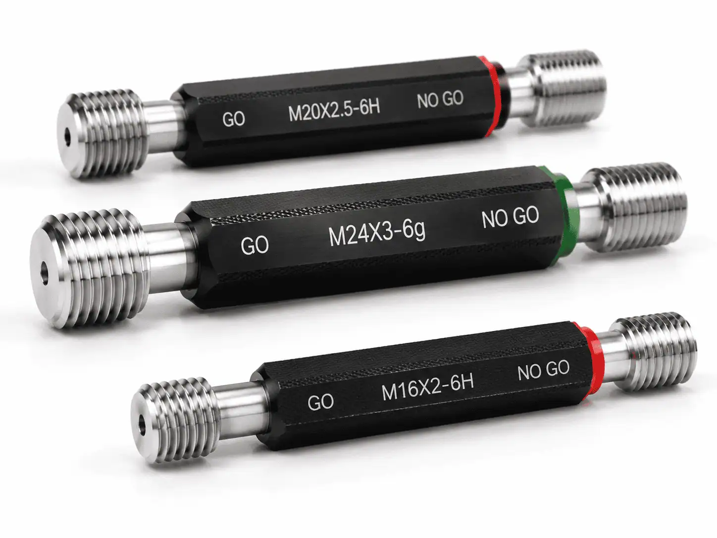
Need gauges for this? GageTools manufactures GO/NO-GO thread plug gauges and thread ring gauges in Dongguan, China. Standard sizes ship from stock within 72 hours, MOQ is 1 piece, and every RFQ gets a reply within 24 hours — request a quote.
Why Gauge Threads During Production
Final inspection finds bad threads after the whole batch is made. In-process gauging finds them while only a few parts are affected. On a CNC line producing hundreds of parts per shift, the difference is a few scrapped parts versus a full pallet of rework or a customer complaint.
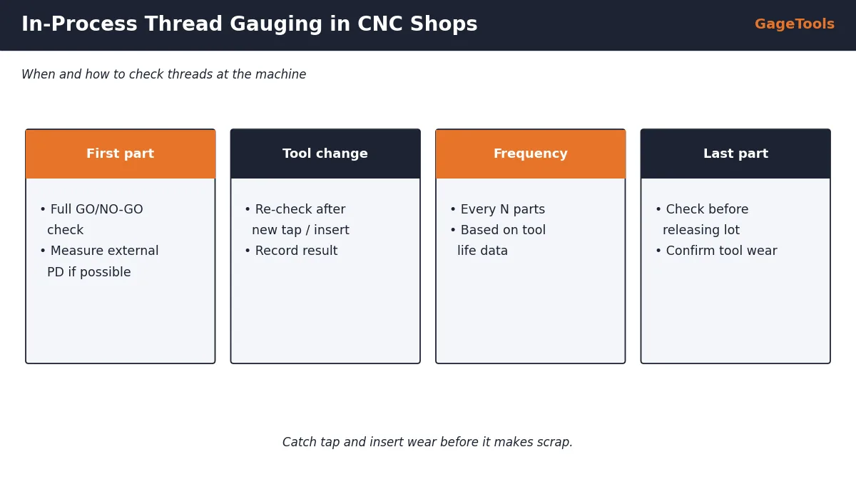
Threads are especially suited to in-process control because they drift in predictable ways. Taps and threading inserts wear, chips pack into blind holes, and offsets are changed. A GO/NO-GO gauge at the machine turns those drifts into an immediate decision the operator can act on.
First-Off Approval
Every setup, program change, tool change or offset change should be followed by a first-off check before production continues.
- Machine the first part and clean the threads of chips and coolant.
- Check with the GO gauge over the full thread length or required depth, by hand.
- Check with the NO-GO gauge, counting turns from first engagement: not more than two under ISO 1502, not more than three complete turns under ASME B1.2.
- Check thread depth, chamfer and position on the drawing where relevant.
- Record the result and the gauge IDs, and have the first-off signed off before running the batch.
If the first part is borderline, with a GO plug that enters but feels tight, do not run the batch. A new tap that already produces a tight thread will only get tighter as it wears.
First-off checks should use the same method as final inspection, so results are comparable. Our step-by-step thread gauge inspection procedure can be used as the basis of the work instruction at each machine, adapted to the part and the control plan.
Setting the Gauging Frequency
There is no universal frequency. It should be based on how fast the process drifts and how many parts you can afford to contain if a check fails.
| Situation | Typical approach |
|---|---|
| New process or new tool type | Frequent checks, e.g. every few parts, until wear behaviour is known |
| Stable process with known tool life | Checks at fixed intervals well inside the tool life |
| Tool near end of planned life | Increase frequency or change the tool early |
| After any tool change, offset change or crash | First-off check again |
| Safety-critical threads | High frequency or 100% gauging, per customer requirement |
| End of batch | Last-off check to confirm the whole batch is covered |
A practical rule: the interval between checks defines how many parts you must re-check if a check fails. If containing 200 parts is unacceptable, check more often than every 200 parts.
Review the frequency regularly. When records show that tools always reach their planned life without a failed check, the interval can be extended with care; when failures appear, shorten it straight away and find out why.
Do not skip the last-off check. Without it, every part made since the last good check is unverified, and a tap that broke or wore out near the end of the batch goes undetected.
Tap Wear, Insert Wear and What the Gauge Shows
Understanding how tools wear helps operators read the gauge before it fails.
A cutting tap usually produces a smaller thread as its cutting edges wear, so the GO plug gets harder to enter. A worn threading insert on a lathe removes less material, so external threads grow and the GO ring gets tight. With thread milling, tool wear can often be corrected by a radius offset; with a tap it cannot.
NO-GO failures are less common in a stable process but point to different causes: an oversize tap, a wrong tap class (for example a tap intended for a looser class), chips recut in the hole, axial misalignment or bell-mouthing at the thread start. For external threads, an undersize thread is often an offset error.
Keeping Gauges at the Machine
In-process gauges live in a harsh place: coolant, chips, heat and busy operators. A few rules keep them reliable:
- A dedicated, labelled gauge holder at each machine, with GO and NO-GO in separate positions.
- Clean the gauge and the part before each check; blow chips out of blind holes.
- Hand pressure only; never use the spindle, a wrench or a tap handle to drive a gauge.
- Wipe and lightly oil gauges at the end of the shift, and store them in their case.
- Keep a spare calibrated set so a damaged gauge does not stop the line or tempt anyone to use it.
Machine-side GO plugs wear faster than any other gauge in the plant. Set their calibration interval by usage, and read our guide to thread plug gauge wear limits so the lab knows what to look for.
Writing a Reaction Plan Operators Can Follow
A reaction plan tells the operator exactly what to do when a gauge check fails. It must be simple enough to follow at 3 a.m. without calling an engineer.
- Stop the machine
- Clean and re-check the part; confirm the gauge is correct and undamaged
- Quarantine all parts since the last good check
- 100% gauge the quarantined parts
- Replace the tap or insert, or correct the offset
- Run a new first-off before restarting
Record the failure, the number of parts contained and rejected, and the cause. If the same failure repeats, shorten the check interval or the planned tool life.
Records, Trends and Attribute Data
GO/NO-GO checks produce attribute data, so classical variable SPC charts do not apply directly. That does not mean the records are useless.
| Record | Use |
|---|---|
| Check time and part count | Shows the check frequency was followed |
| Result (pass / fail) and gauge IDs | Links parts to calibrated gauges |
| Operator remarks, e.g. “GO tight” | Early warning of tool wear before failure |
| Tool change log | Shows actual tool life versus planned life |
| Reaction plan records | Containment and root cause evidence |
Operator remarks such as “GO slightly tight” are valuable. If they appear at a consistent part count, you have found the real tool life and can plan tool changes before any part fails. For control plans under IATF 16949, record the method, frequency and reaction plan for each thread characteristic.
What to Send When Ordering In-Process Thread Gauges
For machine-side gauges, order enough sets for every machine plus spares. Our GO/NO-GO thread gauges are available from MOQ 1, and standard sizes ship from stock within 72 hours. Send us:
- Thread designation and class for each part, e.g. M12x1.75-6H, 5/16-18 UNC-2A
- Number of machines and spare sets required
- Required GO plug length for deep or blind holes
- Whether threads are gauged before or after coating
- Certificate requirement (ISO/IEC 17025 calibration certificate available on request)
For special threads or non-standard lengths, see custom thread gauges from drawing. Send the drawing and we will confirm the gauge design before quoting.
Equipping a CNC Line With Thread Gauges?
Send the thread callouts, classes and number of sets. We reply with price and lead time within 24 hours.
Related: GO/NO-GO thread gauges · Plug gauge wear limits · Rush order thread gauges
Frequently Asked Questions
✓ 20+ years gauge manufacturing
✓ ISO 9001:2015 certified
✓ In-house CNC grinding & inspection
✓ Drawing / RFQ reply within 24h
Order GO/NO-GO Thread Gauges for Your CNC Line
GageTools manufactures GO/NO-GO thread plug and ring gauges for metric, unified, pipe and special threads, supplied per machine with spare sets. ISO/IEC 17025 calibration certificate available on request. Standard sizes ship from stock within 72 hours; custom gauges in 10–15 working days. MOQ 1 piece. WhatsApp for fastest response.
💬 WhatsApp Quote 📐 Send Drawing for Quote